Description
GM328A Transistor Diode LCD Tester LCR Capacitance ESR Voltage Frequency Meter PWM Square Wave Signal Generator Electronic Kits
Note: Some features are not available in the Russian version, please choose to purchase according to your needs~!
Product parameters
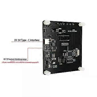
Input voltage: Type -C DC5V
Self welding: DC 9V connector
(DC 9V: requires self welding of connectors before use)
Operating voltage: 30mA approx.
Transistor tester control
1.The tester is controlled by a rotary encoder switch.
2.The rotary encoder switch can be operated in a total of 6 ways, short press, long press, left turn, right turn, press and hold left turn, press and hold right turn.
3.A short press in the off position turns the power on and starts the test.
4.After a test has been completed, if no device is detected. Press and hold the switch or rotate the switch left or right to enter the function menu. Once in the function menu, the left or right switch can be rotated up or down through the menu items, to enter a particular function item, press the switch once short. When it is necessary to exit from a certain function, then press the switch long.
Test Devices
The tester has 3 test points, TP1, TP2 and TP3, which are distributed in the test stand as follows
On the right hand side of the test stand are the test positions for the SMD components, with the numbers 1,2,3, each representing TP1, TP2 and TP3 respectively.
When testing components with only 2 pins, the pins are not divided into test order, 2 pins are chosen for any 2 test points, and the pins of 3-pin devices are placed in three test points, in no particular order. After the test, the tester automatically recognises the pin name of the component, the test point where it is located and displays it on the screen.
When testing components with only 2 pins, if two test points are used, TP1 and TP3, the tester automatically enters continuous test mode after the test is completed, so that the components on TP1 and TP3 can be measured continuously and simultaneously without having to press the switch again. If "TP1 and TP2" or "TP2 and TP3" are used, only one test is performed. To test again, press the switch once.
Note:
Before testing the capacitor, discharge the capacitor before inserting it into the test holder for measurement, otherwise there is a risk of damaging the tester's microcontroller.
1,Calibration
The tester calibration is used to eliminate errors in its own components, making the final test results more accurate. Calibration is divided into quick calibration and full function calibration.
The operation method for quick calibration: short the three test points TP1, TP2 and TP3 with wires and then press the test button while watching the screen. The screen colour will change to white text on a black background. After the prompt message "Selftest mode...? ", press the test button to enter the fast calibration process; if, after the message "Selftest mode...? If no button is pressed within 2 seconds after the message "Selftest mode...", the normal test process is carried out and the resistance values of the three test points TP1, TP2 and TP3 are displayed at the end. After entering the quick calibration process, some data will appear on the screen, ignore it. Wait until a flashing string appears on the screen
After "isolate Probes!", remove the shorted TP1, TP2 and TP3 leads. The quick calibration is complete until the string "Test End" appears on the screen. When calibrating for the first time, use the full function calibration method.
The full function calibration is accessed from the function menu and requires an additional 220nf capacitor. Full function calibration performs a more comprehensive calibration process and can take longer. Once in the function menu, turn the test button to the menu item "Selftest", then press the test button to enter the full function calibration process, which starts with the flashing string "short Probes! When the flashing string "isolate Probes!" appears on the screen, remove the wires from the three test points and continue to wait for the calibration process to proceed, when the string "1-||- 3 > 100nf", install the prepared 220nf capacitors on test points TP1 and TP3. Wait until the screen says "Test End" and the fully functional calibration process is complete.
2. Function menu
2.1 Switch off
2.2 Transistor
2.3 Frequency
Measures the frequency. Press and hold the test button to exit the frequency measurement function. The frequency measurement range is from 1 Hz to more than 1 MHz, when the measured frequency is below 25 KHz, the period is displayed
2.4 f-Generator
Square wave generator with multiple square wave frequencies selectable, turn the test button left or right to switch between different square wave frequencies, long press the test button to exit the square wave generator.
2.5 10-bit PWM
Pulse generator, left or right turn the test
-
Fruugo ID:
405876432-860618363
-
EAN:
7617000533532
Product Safety Information
Please see the product safety information specific to this product outlined below
The following information is provided by the independent third-party retailer selling this product.
Product Safety Labels

Safety Warnings:
WARNING! TO AVOID DANGER OF SUFFOCATION,KEEP AWAY FROM BABIES ANDCHILDREN. DO NOT USE IN CRIBS/BEDSOR PLAY PENS.THIS BAG IS NOT ATOY.
Ingredients:
Octinoxate 5.2867%
Manufacturer Part Number:
JK203027
Model Number:
JK199930
Serial Number:
JK062427
Batch Number:
JK197038